Ac To Dc Converter Using Igbt

Shows The Three Phase Bidirectional Ac Dc Converter Topology Which

Overview Of Design Examples Of Ac Dc Non Isolated Buck Converters

Circuit Diagram Of Proposed Single Stage Ac Dc Converter With Pfc
Pdf Simulation Of Closed Loop Ac Dc Converter For Power Quality

What Is Switching System Basic Knowledge Rohm Tech Web

Ac Dc Converters Including Buck Boost And Flyback
Dc voltage is used to get controlled dc voltage output using an igbt with a pulse of variable duty cycle generated by a microcontroller.
Ac to dc converter using igbt. How pwm convert dc into ac. Pwm based inverter is used in vfd variable frequency drive. By varying the duty. An ac to dc converter furnishing a regulated dc output voltage from an ac input supply voltage which is converted with a rectifier that utilizes in at least two of its legs igbt insulated gate bipolar transistor devices preferably of the kind that have no internal diodes.
Igbt based pulse width modulation pwm inverter working concept is explained in the video tutorial. Powering igbt gate drives with dc dc converters 01 05 2014. Controlled semiconductor devices such as transistors scr and gto thyristors are used in inverters. When the insulated gate bipolar transistor igbt was invented by professor jayant baliga in 1980 it was seen as an ideal combination of the low on state saturation voltage of a bipolar transistor and ease of gate drive of a mosfet.
C1 is charged through d1 and r1 when q2 is on. The purpose of a dc to ac inverter is to convert dc voltage to a pure sinusoidal output voltage in applications such as ups solar inverter and frequency converter. Figure 3 3 circuit diagram of an ac to dc converter using microcontroller 17 figure 4 1 simulation circuit in multisim 19 figure 4 2 output for a load of 1k ohms and duty cycle 90 20. Alternatives to isolated dc dc converters it is not always necessary to use isolated dc dc converters to provide drive power to igbts.
If isolation is not required then a cheap and simple charge pump can suffice as shown in figure 3. Also included in the converter of this convention is circuitry which tracks zero crossing events relative to ac input. Three level three phase sic ac to dc converter reference design ti designs. Tida 010039 three level three phase sic ac to dc converter reference design.
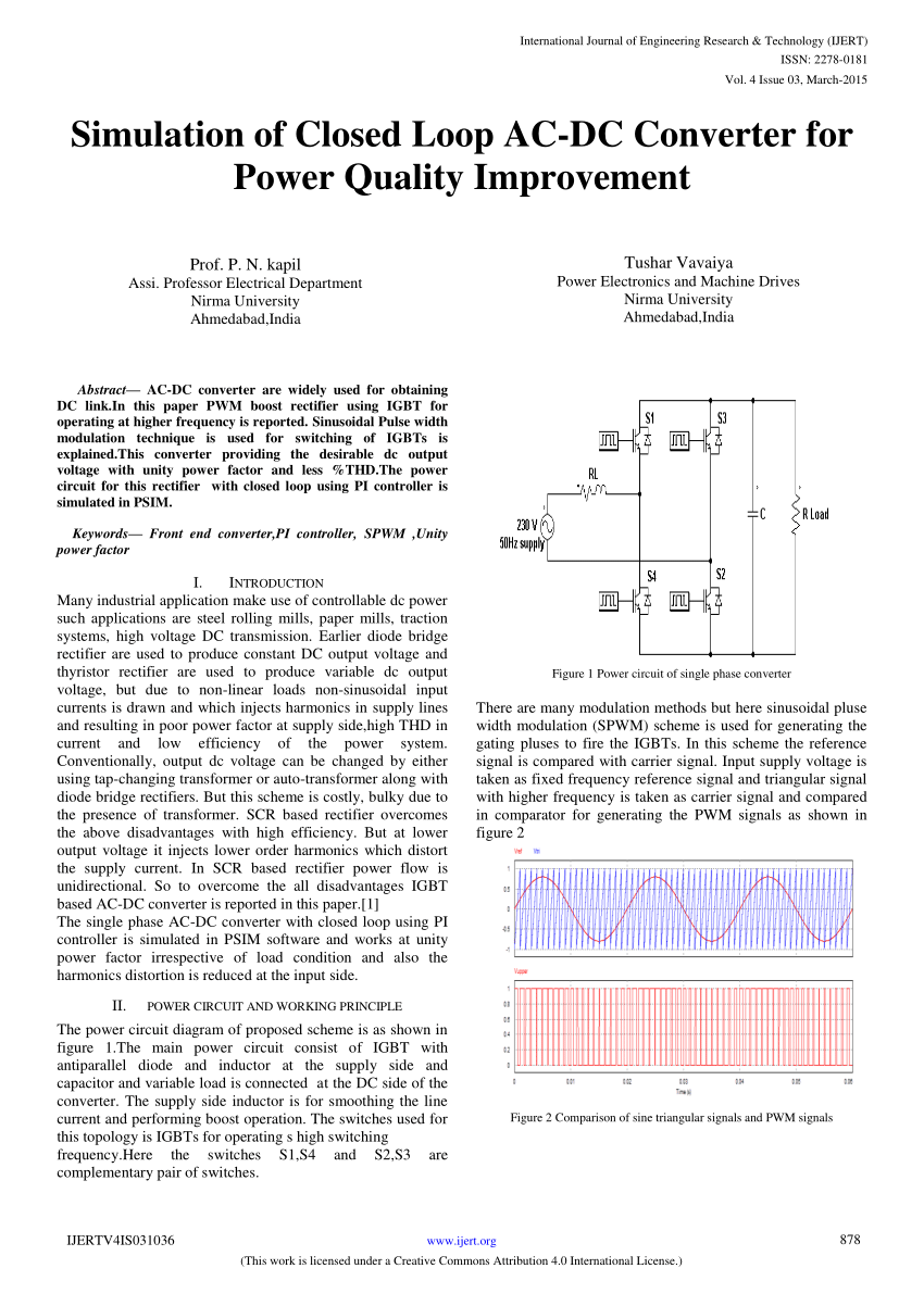
3 phase igbt converter with power circuit and control electronics control electronics converter control measurements driver interface aux. Power supply external control power circuit dr1 dr2 dr3 dr4 dr5 dr6 dc link ac link current valve igbt fwd snubber circuit gate driver output filter.

Design Of Ac Dc Power Converters With Lcl Tuned Trap Line Filter

The Strucutre Of The Ac Dc Ac Electrical Railway Traction System

Ac Dc Three Level Pwm Converter Matlab Simulink

Board Mount Ac Dc Converter Design Challenges Recom

Pdf A New Ac Dc Converter Using Bridgeless Sepic

Pdf Study Of A Single Phase Bidirectional Ac Dc Converter With A

Improving The Efficiency Of Ac Dc Converters Through Synchronous

Ac Dc Converter With A Ups Placed On The Secondary The Ups Is A

How To Make Ac To Dc Converter At Home Youtube
Electronics Free Full Text A Buck Boost Transformerless Dc Dc

Schematic Diagram Of Ac Dc Buck Boost Converter Fed Dc Motor

Firing Angle An Overview Sciencedirect Topics

Pin Em Fuente Pwm
